Code and diagrams to build an Arduino-based infrared light bridge and relay circuits for 1:32 scale slotcar track using the Ultimate Racer RMS. This was used to build a 4 lane track for the Tiny Riders in Milwaukee, WI, USA. Code, diagrams, and information can be adapted for different scenarios, number of lanes, etc.
Check the arduino-code folder for the source. You will also need to use the UnoJoy project so that the Arduino appears as USB HID-compliant device. The Ultimate Racer RMS software can only interface in a limited number of ways. We didn't want to use parallel port or serial port methods as they proved problematic in the past and usually required antiquated hardware. The Arduino will appear as a PS3 stlye gamepad to the computer to send race events to Ultimate Racer. Getting events out of Ultimate Racer is a bit challenging because few interfaces are supported. To get around this problem, the Arduino controls the open/closed state of the relay circuit and only sends signals into Ultimate Racer to pause the heat if a car gets deslotted. The Arduino is connected to a 5v relay (shown as 3.3 in diagram -- either is fine and supported by the Arduino). The 5v relay then triggers 2 12v relays to control power to the lanes.
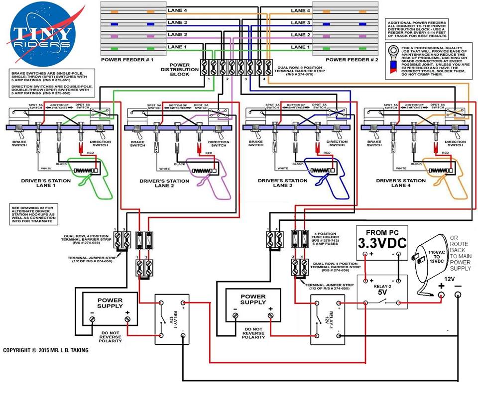
We used 2 power supplies each running at 14v each powering 2 lanes in the configuration. Make sure to put fuses (we used 4 amp) or thermal protection on the circuit or you can damage your controllers.
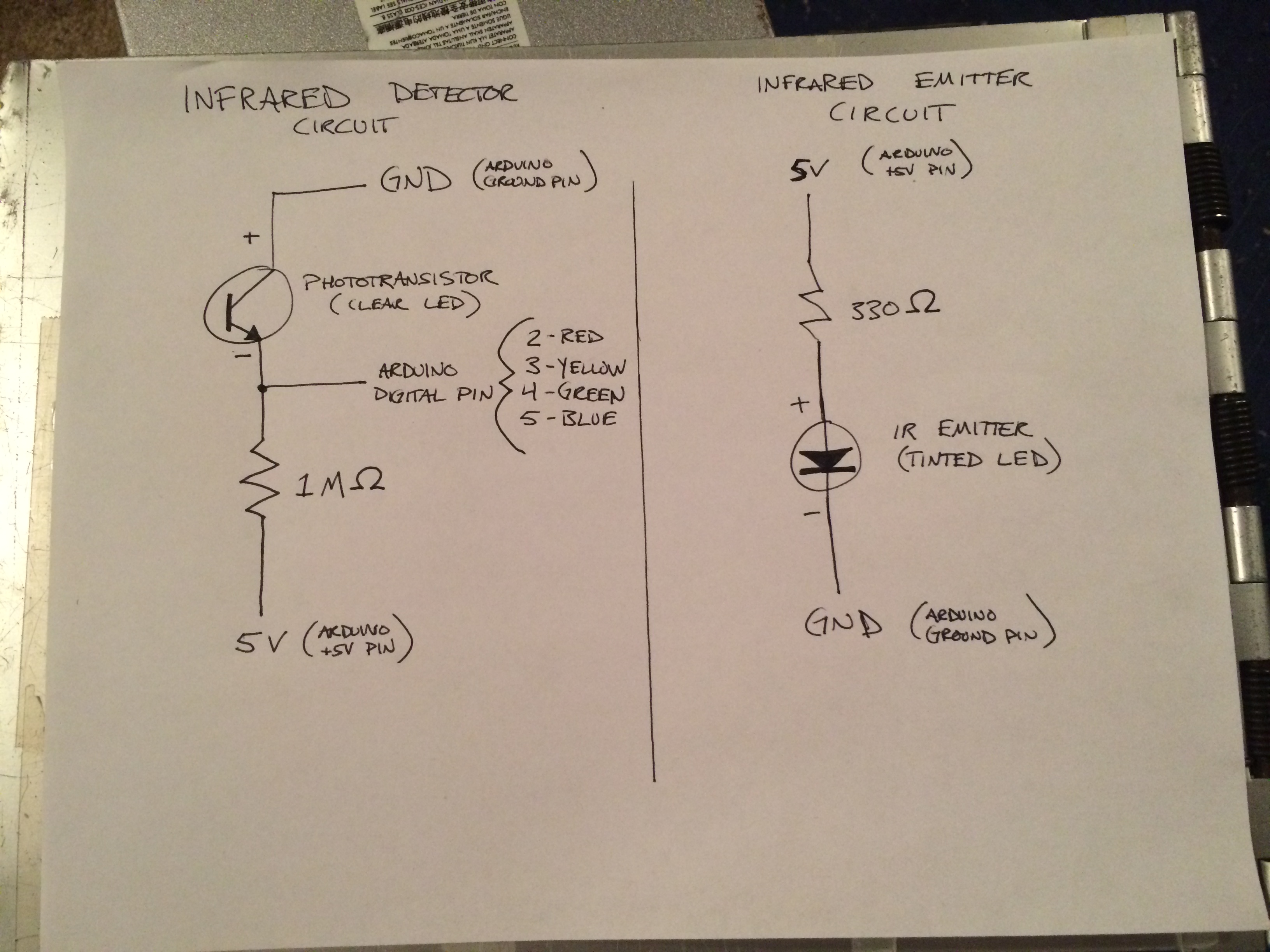
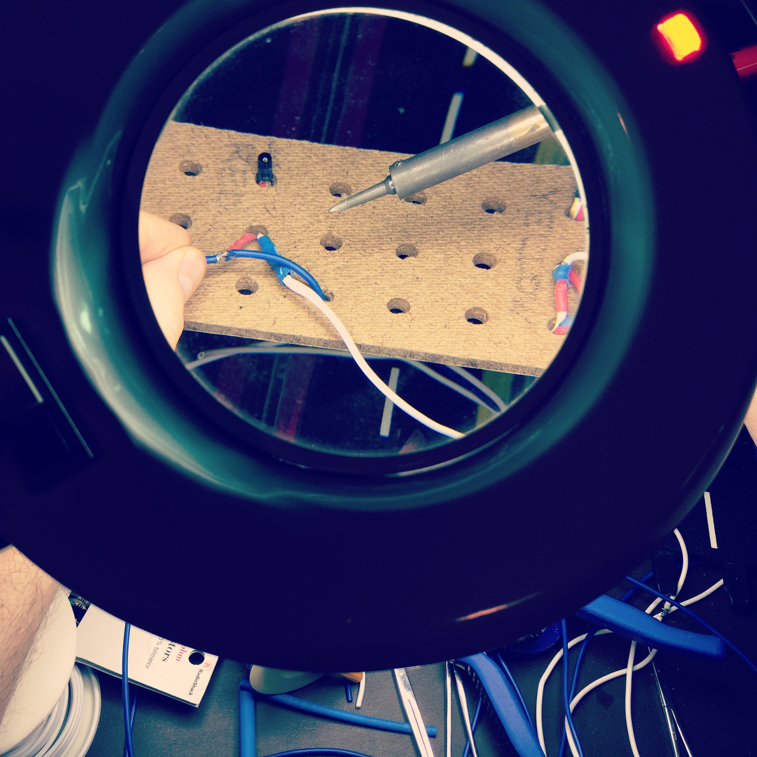
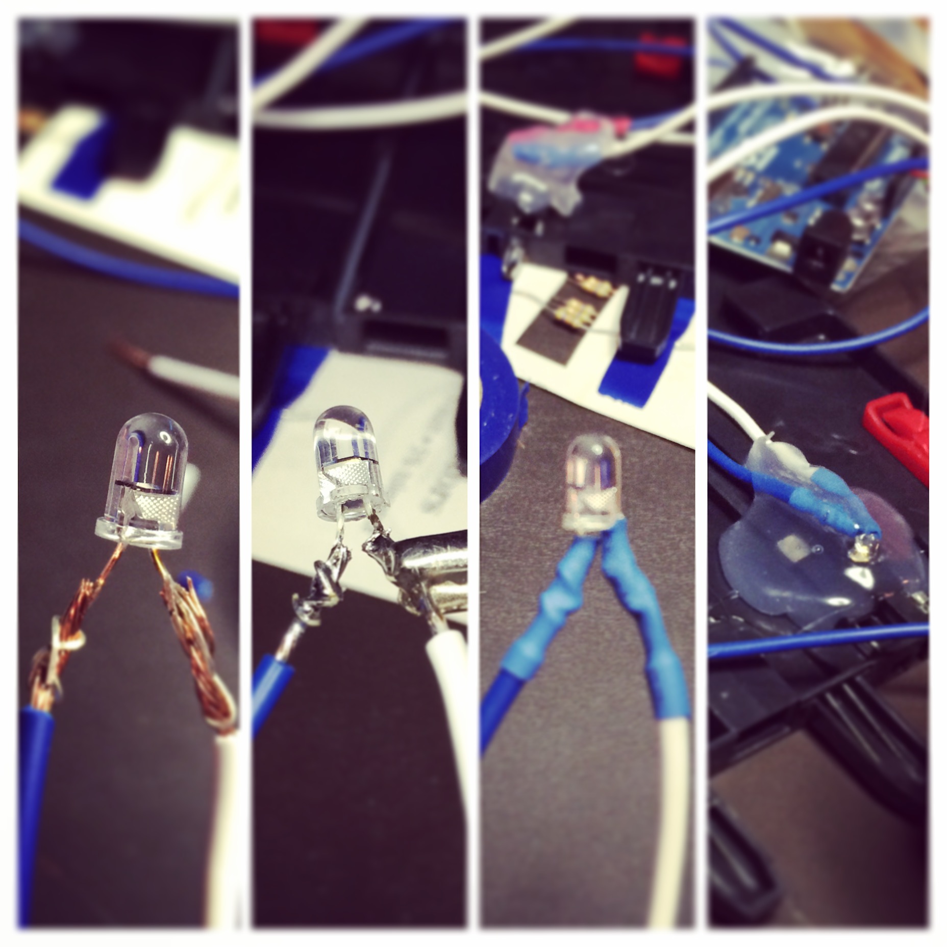
We use an infrared beam from a bridge to detect when each lane has completed a lap.